
11May
Standard Installation Guideline for Chemical Earthing System
1. Pre-Installation Planning
1.1. Site Survey & Soil Resistivity
- Conduct a soil resistivity test using the Wenner Four-Point Method at the intended location to determine the expected depth and number of electrodes required.
1.2. Location Selection
- Moisture: Choose an area where the soil naturally retains moisture (e.g., near water pipes, shaded areas).
- Proximity: Install as close to the electrical panel/ equipment as possible to minimize the length of the earth conductor.
- Clearance: Maintain a safe distance from building foundations (minimum 1.5 meters) to avoid structural contact during thermal expansion or lightning strikes.
- Isolation: Do not install in areas prone to heavy vehicle traffic or where chemical spills (acids/alkalis) are likely.
1.3. Electrode Spacing (For Multiple Electrodes)
- If installing multiple electrodes to achieve target resistance, the distance between two electrodes must be at least twice the length of the electrode (e.g., 3m electrode = minimum 6m spacing).
2. Tools & Materials Required
- Auger boring machine or manual earth auger / spades.
- Measuring tape and plumb line (for vertical alignment).
- Chemical Earthing Electrode assembly.
- Quality Backfill Compound (Bentonite / Marconite / proprietary mixture).
- Clean, soft water.
- Funnel or pouring shovel.
- Earth resistance meter (3-point or 4-point tester).
- Exothermic welding kit or heavy-duty brass bolts/clamps.
- Anti-corrosion jointing tape (for exposed connections).
3. Step-by-Step Installation Procedure
Step 1: Excavation (Boring the Pit)
- Bore a hole into the ground using an auger.
- Diameter: The hole should be 150mm to 200mm (6 to 8 inches) larger than the outer diameter of the chemical electrode.
- Depth: Bore to the required depth (typically 2.5 meters to 3 meters, depending on the electrode length). Ensure the bottom of the bore is flat and free of hard rocks.
Step 2: Preparation of Backfill Compound
- Note: Always follow the specific compound manufacturer’s instructions, as ratios vary.
- For Bentonite-based compounds: Mix the dry powder with clean water in a bucket to create a thick, lump-free slurry. Allow it to sit for 15-20 minutes to fully absorb water and expand.
- For Marconite-based compounds: Mix the compound with a specific ratio of clean water (e.g., 1 part water to 3 parts compound by weight) to form a damp, thick paste.
Step 3: Base Bedding
- Pour a layer of the prepared chemical compound slurry/paste (approx. 100mm to 150mm thick) into the bottom of the borehole.
- This creates a conductive cushion at the bottom.
Step 4: Electrode Insertion
- Carefully lower the chemical earthing electrode into the center of the borehole.
- Use a plumb line to ensure the electrode is perfectly vertical. A tilted electrode can touch the sides of the earth pit, defeating the purpose of the chemical compound layer and causing uneven current dissipation.
- Place a wooden or concrete support across the top of the pit to hold the electrode in the exact center while backfilling.
Step 5: Backfilling the Pit
- Pour the prepared chemical compound mixture evenly around the electrode into the annular space (the gap between the electrode and the soil wall).
- CRITICAL: Do not dump dry powder directly into the hole and then flood it with water. This creates air pockets, which are terrible conductors and can lead to uneven settling later.
- Tamp (gently pack) the compound at intervals of 150mm to ensure no air voids are trapped.
- Continue this process until the borehole is completely filled to ground level.
Step 6: Final Covering
- Once the chemical compound reaches ground level, cover the top with a layer (approx. 100mm) of normal excavated soil or fine sand.
- Create a slight mound/dome shape over the pit. This prevents water from pooling directly over the electrode, protecting the top cap from direct erosion.
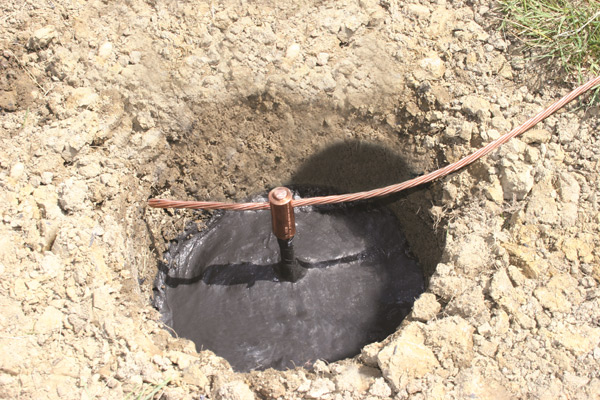
Step 7: Making the Connections
- Connect the primary earth conductor (usually copper or GI strip) to the electrode’s top terminal.
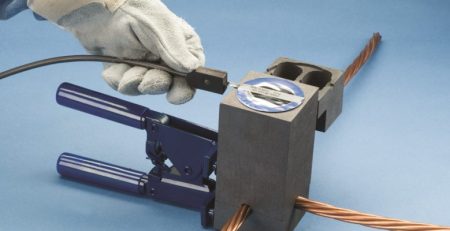
- Best Practice: Use Exothermic Welding for the connection to ensure a molecular bond that will not loosen or corrode over time.
- Alternative: If bolting is used, apply a layer of anti-corrosion grease, wrap the joint heavily with Denso tape, and then PVC tape to protect it from moisture and soil chemicals.
4. Testing & Commissioning
4.1. Curing Time
- Do not test the electrode immediately. The backfill compound needs time to set and bond with the surrounding soil.
- Wait a minimum of 48 to 72 hours after installation before taking resistance readings. For Bentonite, a wait of 7 days is ideal to allow full moisture absorption.
4.2. Resistance Testing
- Use the Fall of Potential (Three-Point) Method to measure the earth resistance.
- The target resistance should be as per the specific project requirement or standard (e.g., < 1 Ohm for substations/towers, < 5 Ohm for general industrial, < 10 Ohm for domestic as per IS 3043).
- Note: If the target is not met, do not dig up the electrode. Instead, install additional electrodes in parallel as per the spacing rule in Section 1.3.
5. Safety Precautions
- Underground Utilities: Before digging, strictly verify that there are no underground power cables, water pipes, or gas lines in the vicinity. Use a cable detector if necessary.
- PPE: Wear safety boots, gloves, and safety goggles during excavation and handling of chemical powders (to prevent eye/skin irritation from Bentonite dust).
- Shoring: If the soil is very loose or sandy, use shoring or a casing pipe during excavation to prevent the pit from collapsing.
6. Maintenance Schedule (“Maintenance-Free” Clarification)
While termed “maintenance-free,” chemical earthing systems require periodic verification:
- Visual Inspection (Annually): Check the top of the electrode for physical damage, check that the mound is intact (preventing water pooling), and inspect the exposed connections for corrosion.
- Resistance Testing (Annually): Measure the earth resistance during the driest season of the year to ensure the system is performing within safe limits. If resistance rises, it indicates a drop in the water table, requiring the addition of water via an auxiliary watering pipe (if provided in the electrode design).
Document Reference: IG-CHE-001 Applicable Standards: IS 3043, IEEE Std 80, IEC 62305, NBC (National Building Code) Scope: This guideline covers the step-by-step procedure for the correct installation of maintenance-free chemical earthing electrodes (Copper Bonded/GI with backfill compounds like Bentonite/Marconite) to ensure long-term reliability and low earth resistance.


Leave a Reply